Beginner workshop
The beginner workshop builds a panel that includes toggle switches, illuminated push buttons, and an encoder to control a parking brake and autopilot heading, and to display the current state of the parking brake.
There are two versions of the workshop kit, which differ in the included LED push buttons:
Required components
The following components are required for the project:
| Part | Quantity |
|---|---|
| Mega 2560 Pro Mini | 1 |
| MobiFlight prototyping board | 1 |
| Enclosure | 1 |
| LED push button | 2 |
| Encoder with breakout board | 1 |
| ON-ON switch | 2 |
| MobiFlight switch breakout board | 1 |
| XH-JST 2-pin wire (soldered to push button) |
4 |
| XH-JST 3-pin wire | 2 |
| XH-JST 4-pin wire | 1 |
| M3x5mm screw | 8 |
| Part | Quantity |
|---|---|
| Mega 2560 Pro Mini | 1 |
| MobiFlight prototyping board | 1 |
| Enclosure | 1 |
| LED push button circuit board | 1 |
| Encoder with breakout board | 1 |
| ON-ON switch | 2 |
| MobiFlight switch breakout board | 1 |
| XH-JST 2-pin wire | 4 |
| XH-JST 3-pin wire | 2 |
| XH-JST 4-pin wire | 1 |
| M3x5mm screw | 12 |
3D-printed enclosure parts
The following parts make up the 3D-printed enclosure:
Assembling the boards
To assemble the prototyping board and Mega 2560 Pro Mini, connect the Mega to the back of the prototyping board. Then, connect one end of the USB cable to the Mega and the other end of the cable to your computer.
Installing the firmware and board configuration
Install MobiFlight
Use the getting started guide to install MobiFlight.
Upload the firmware
Follow the flashing ambiguous boards guide to upload the correct firmware to the Mega 2560 Pro Mini.
Upload the board configuration
Use the installing configuration guide to upload the standard configuration for a prototype board to the Mega.
Assembling and connecting the LED buttons
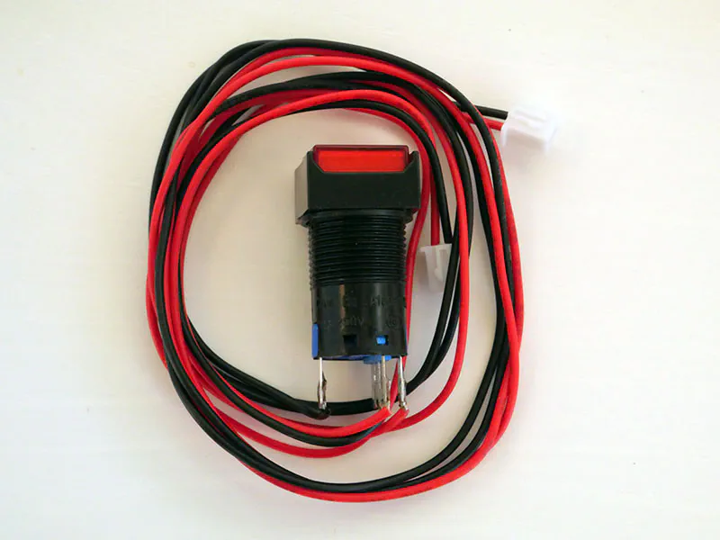
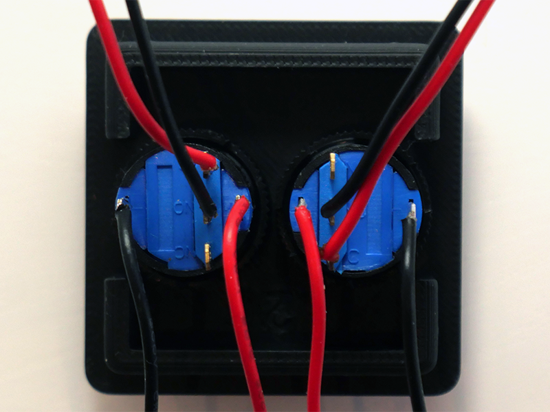
Take the red LED button. Remove the plastic nut and the metal plate. Put the metal plate away, it is not needed for this assembly.
Take the 3D-printed button lid. Pull the wires through the left hole, then insert the switch through the same hole so that the row of three contacts is closest to the middle of the lid.
Pull the wires through the plastic nut and tighten the nut against the switch. The cutout in the lid will help you reach the nut.
Repeat the same procedure with the orange switch, using the right hole in the lid. When you are finished, the assembly should look like this:
On the case, find the hole with the two slots on the sides. Thread each of the wires through that hole as you connect the buttons to the prototyping board.
Begin by connecting the buttons. The wires for the buttons are connected to two contacts (labeled C and NO) on the row of three. Connect the red button to Button 1 on the prototyping board, the orange button to Button 2.
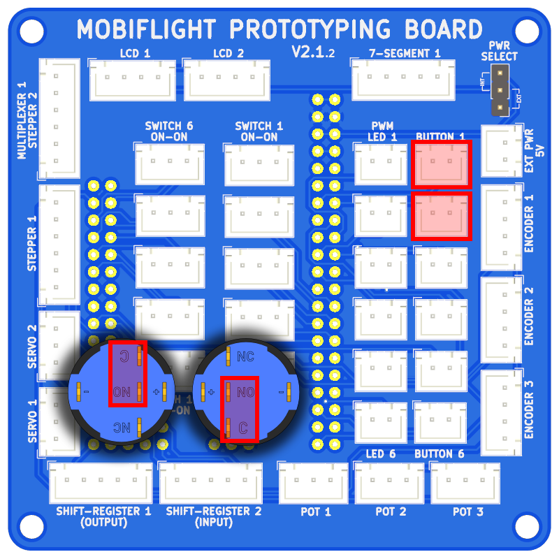
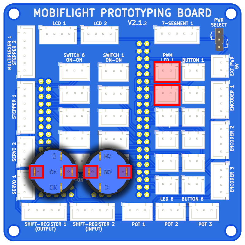
Then connect the LEDs. The wires for the LEDs are connected to the two contacts on the outer edges of the switches. Connect the red LED to PWM LED 1, the one underneath to PWM LED 2.
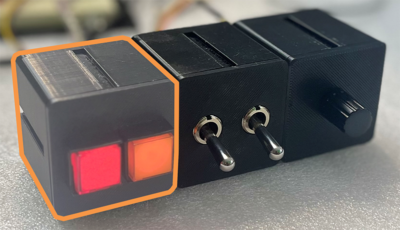
With all wires connected, push the lid into the case such that the red button is on the left edge of the case and the orange button faces towards the next opening.
Place the circuit board into the lid such that both the text on the lid (if present) and the labels on the board are facing upwards. The buttons should be aligned with the holes in the lid.
Use four M3x5mm screws to secure the circuit board to the lid. Be sure not to overtighten the screws to avoid damaging the plastic threads.
On the case, find the leftmost hole. Thread each of the wires through that hole as you connect the buttons to the prototyping board.
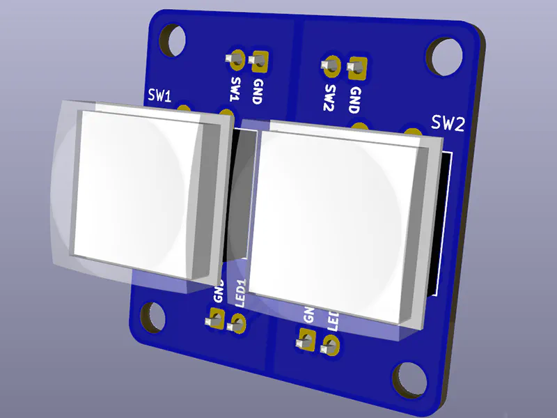
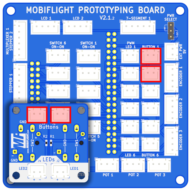
Take one of the 2-pin cables. Plug it into the top-right JST-XH connector on the button board. The connector is on a blue background near the Buttons label, and on the same side as the SW1 label. Pull the wire through the hole in the case, then plug it into the Button 1 connector on the prototyping board. Repeat the process for the other Buttons connector, plugging the other end into the Button 2 socket.
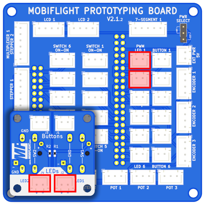
Repeat this procedure for the LEDs. One cable connects LED1 on the button board with PWM LED 1 on the prototyping board, the other connects LED2 with PWM LED 2. The LED connectors on the button board are easily identified by their white background.
With all wires connected, push the lid into the case such that the labels on the lid are readable with the lid on the left.
Assembling and connecting the toggle switches
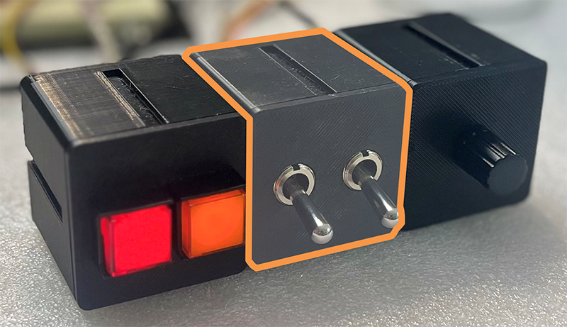
Assemble the toggle switches into the case by screwing a nut halfway down the threads on each switch. Place both switches on the PCB, then use M3 screws to attach the PCB to the back of the lid. Pass the cable through the hole in the back of the case, then close the lid.
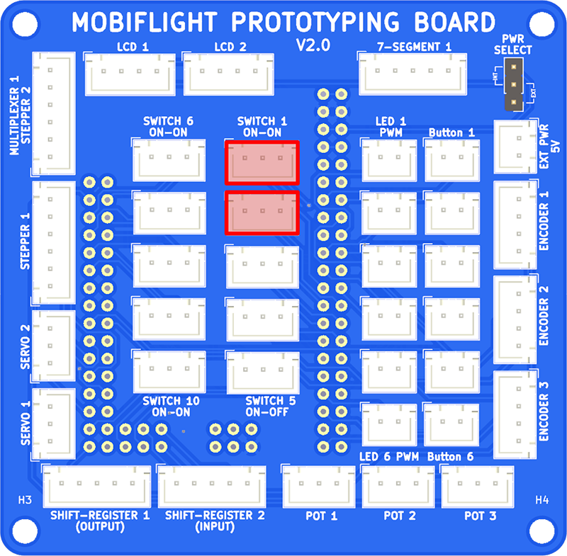
The switches are connected using two XH-JST 3-pin cables. Connect the first switch to SWITCH 1 ON-ON and the second switch to SWITCH 2 ON-ON on the breakout board.
Assembling and connecting the encoder
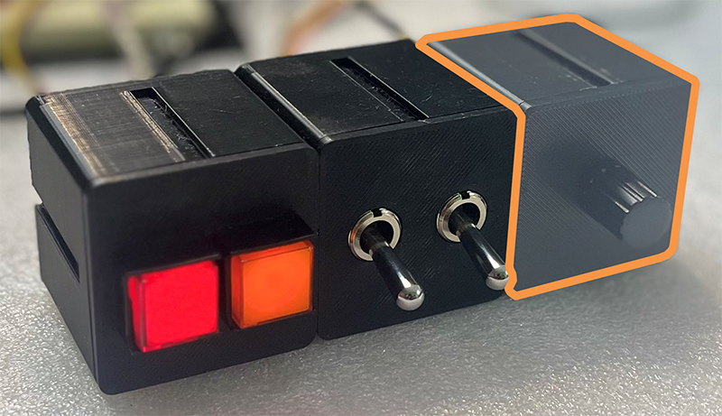
Assemble the encoder into the case using M3 screws to attach the PCB to the back of the lid. Pass the cable through the hole in the back of the case, then close the lid.
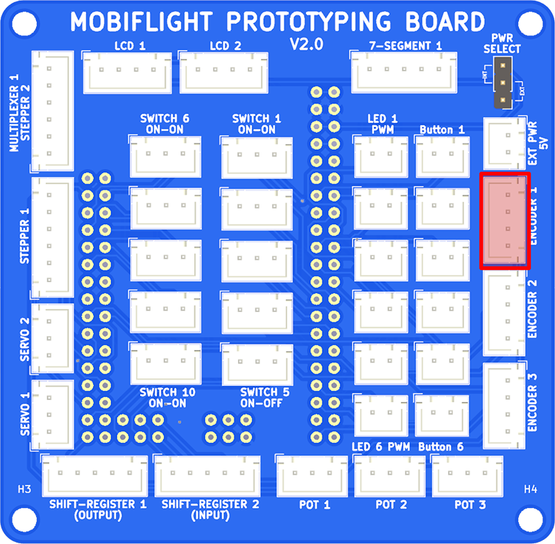
The encoder is connected using one XH-JST 4-pin cable. Connect the encoder PCB INNER SHAFT connector to Encoder 1 on the breakout board.
Configuring MobiFlight
The inputs and outputs are configured in MobiFlight by following the guides for each device type:
| Device description | Device name | Guide |
|---|---|---|
| Red button LED | LED 1 | Configuring LEDs |
| Red button | Button 3 | Configuring buttons |
| Toggle switch | Button 3 | Configuring two-position switches |
| Encoder | Encoder 1 | Configuring encoders |
Next steps
With the project assembled, run Microsoft Flight Simulator, spawn in an aircraft like the Cessna 172, ensure the Run button is active in the MobiFlight toolbar, and try everything out.
Learn more about using MobiFlight in the getting started guide, discover additional supported devices, and join the MobiFlight Discord to share your project with other enthusiasts.